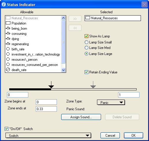
Use the Status Indicator dialog box to view and edit the properties of the selected status indicators.
To open the Status Indicator dialog box, double-click the status indicator icon on the Interface layer, or select the status indicator and then choose Open Selection from the Interface menu (or right-click the status indicator icon and then choose Open from the menu that appears).
Note: Some of the options available in this dialog box depend on whether you choose to define the status indicator as a lamp or a speedometer gauge.
Displays the list of all entities that are available to be assigned to the status indicator.
Use this list to select the entity that you want to associate with the status indicator you are defining.
 button. The entity's name turns gray in the "Allowable" list.
 button.
 button.
Displays the name of the entity that is associated with the status indicator.
Use this check box to select the type of status indicator you want to define.
Note: By default, this check box is selected and the status indicator appears as a lamp on the Interface layer.
To define the status indicator as a lamp, select the Show As Lamp check box. A lamp indicator appears as a small circle on the diagram. The lamp uses color only (green, yellow, or red) to report the status of the associated entity. Lamps do an excellent job of letting users know whether there is a problem in the model. They also do an excellent job of conserving screen real estate.

If you select the Show As Lamp check box, select the lamp size by selecting the appropriate option: Lamp Size Small, Lamp Size Med, or Lamp Size Large.
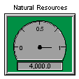
To define the status indicator as a speedometer gauge, clear the Show As Lamp check box. The speedometer shows the magnitude of the assigned entity using both a needle gauge and color. Speedometer gauges provide more information than lamps, at the cost of taking up more room on the model diagram.
Select this check box to display the name of the associated entity above the status indicator in the model diagram. If you do not select this check box, no name appears for the status indicator.
This check box is available only if you defined the status indicator as a speedometer gauge by clearing the Show As Lamp check box.
Select this check box to display the current value of the associated entity at the bottom of the status indicator.
If you select this check box, the Units and Precision options appear. Use these options to specify how you want the current value to appear on the status indicator (for example, you can have the status indicator display the value as a dollar amount or a percentage, with up to two decimal places displayed).
Select this check box to have the status indicator continue to display the final indicator color (and value, if a speedometer) after the end of the run.
If you do not select this check box, the status indicator color is reset to gray at the end of the run and the final value (if a speedometer) is no longer displayed when the run is completed.

The zone continuum is a visual representation of the three zones you can define for the status indicator. The continuum is defined by a minimum and maximum value. Each zone is defined by a beginning and ending value and is associated with a color that displays on the status indicator (green, yellow, and red).
The highlighted portion of the bar at the bottom of the continuum indicates which zone you are defining. The arrows indicate the boundaries between the zones.
Tip: You can also specify the zone beginning and ending values by clicking and dragging the zone boundary arrows.
If you selected Panic as the zone type for the currently selected zone in the zone continuum bar, use the buttons in the section to have a sound generated when the status indicator is in the panic zone.
Select this check box to display a navigation ( ) button on the status indicator.
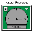
When you click the navigation () button, the software displays the Model layer and highlights the icon for the associated entity.
This check box is available only if you defined the status indicator as a speedometer gauge by clearing the Show As Lamp check box.
Select this check box to associate the status indicator with a defined switch in the model. This allows model users to turn the status indicator on and off. For example, indicators that show the magnitude of wolves in the Greater Yellowstone ecosystem may be relevant only after the predators have ben introduced into the ecosystem.
When the switch is turned off in the model, the associated status indicator is grayed out.